RF · X-BAND · CST STUDIO
8–12 GHz Circular Horn Antenna Design and CST Analysis
The geometry, impedance matching, electric field, and far-field radiation characteristics of an X-band circular horn antenna were studied in CST Studio.
A directional antenna for X-band
The course project modeled a circular horn antenna for operation across 8–12 GHz and studied it in a mobile base-station context. The design focused on directional radiation, low reflection, and numerical inspection of the electric-field distribution.
Geometry and CST model
The waveguide and horn geometry were sized for the target frequency range, using a 75 mm aperture width and 140 mm aperture height in the report. The CST model evaluates S-parameters, VSWR, electric field, and the three-dimensional far-field pattern together.
Simulation results
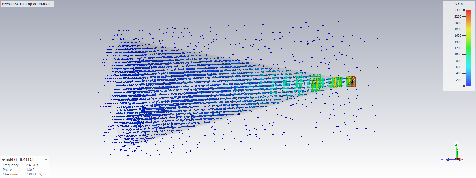
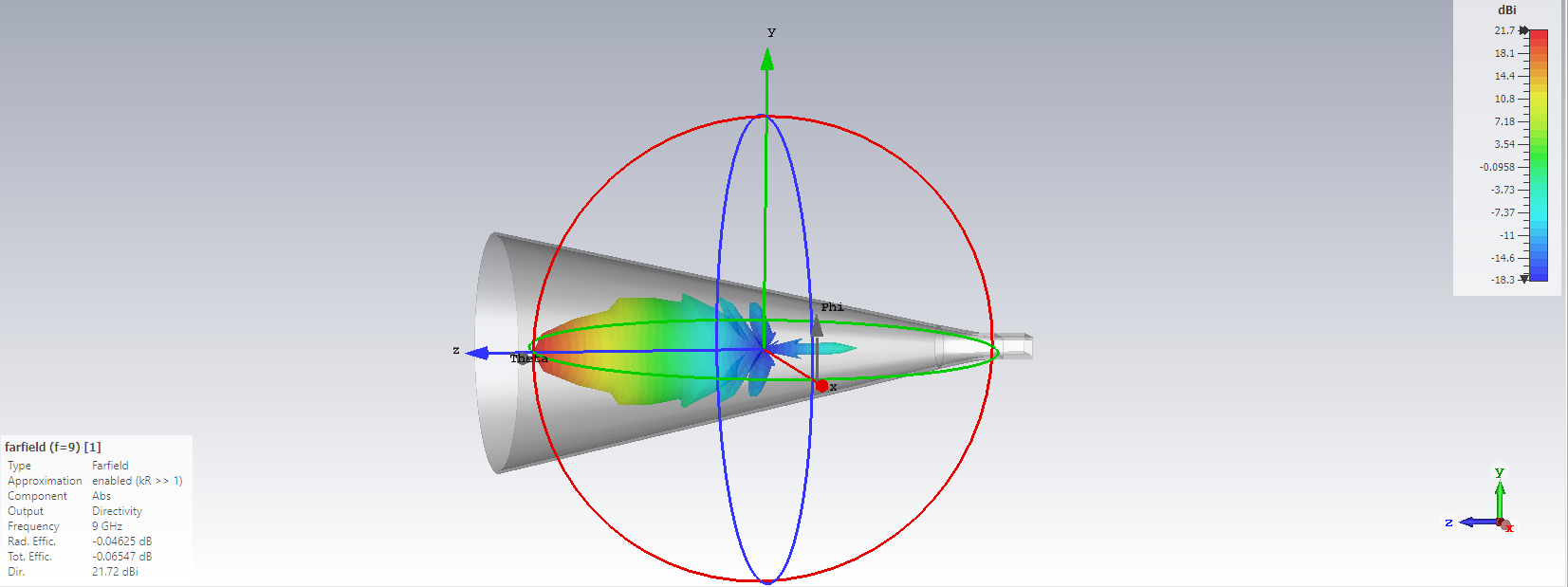
The report records S11 below −10 dB around 8.5 GHz and a maximum directivity of 21.72 dBi. The three-dimensional far-field view shows a clearly directional main lobe, while the electric-field view illustrates field propagation through the horn.
Scope of the exposure calculation
The study also includes a theoretical SAR calculation derived from the electric field. It is treated here as a calculation exercise within the report, not as a calibrated field measurement, accredited compliance test, or health-safety certification.
Where it stands
The project was completed as a CST-based design and simulation study. No antenna was fabricated, and no VNA or anechoic-chamber measurement was performed; the results apply only to the electromagnetic model documented in the report.